The Stairway tool allows you to draw a stairway on the scene.
To activate the Stairway tool, click the  button on the toolbar, or, navigate to Tools | Drawing | Stairway, or use the Alt + R hot key.
Fenix+ 3 provides type-forms to create the following stairway models:
- A custom-shaped stairway from a set of Flights and Landings.
- A Typical two-flight stairway.
- A Spiral stairway.
You can choose flight types with different qualities for all type-forms of the stairways. More on that under Flight Types.
You can arrange Registering Devices in the area where standard (double-flight) stairways and custom-shaped stairways are located. For this, select the desired flight of the required stairway and then select the option With registering device.
If a stairway does not act as a barrier to the spread of dangerous fire factors, it can be disregarded during fire dynamics simulation (see Ignoring Objects in Fire Dynamics Simulation).
In most regulatory documents, the following is not recommended to place on escape routes: the arrangement of curved stairways, stairs with winders, steps with varying tread widths, split-level stair landings, except for curved stairways leading from service areas (excluding buildings of medical institutions) with an occupancy of no more than five people, and curved grand stairways when they meet the requirements of this building’s evacuating code for stairs and stairwells, as well as except in cases provided by regulatory documents on fire safety. If it is necessary to create stairs on escape routes that do not meet the specified requirements, they should not be considered for use in evacuating people in case of a fire and must be blocked off.
Custom stairway
To create a custom-shaped stairway, it is necessary to draw one or several flights and landings on the scene with corresponding parameters.
A stairway is created correctly if the upper level of the landing is located on the same level with the upper or lower level of the flight, and the edges of the flight are adjacent to the edges of the landing.
Flight
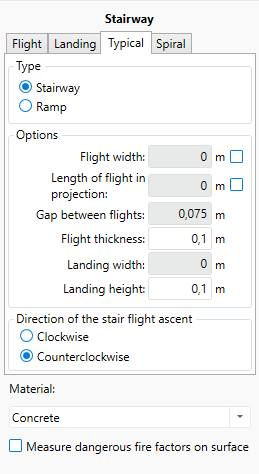
To start creating a flight, switch to the Flight tab, select type Stairway or Ramp, specify width, length or other parameters.
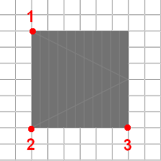
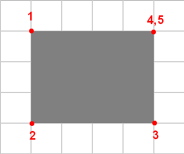
To draw a stair flight:
- Mark the starting drawing point by clicking the left mouse button in the topology editor (mark 1).
- Mark the stair width by clicking the left mouse button the second time (mark 2).
- Mark the stair length and finish drawing by clicking the left mouse button for the third time (mark 3).
 {width=60%}
If width or length in projection parameters are set before drawing, you will be able to change the relation of a model preview to a starting drawing point (mark 1) with the Space key.
If only the width parameter is set before drawing, after creating the starting drawing point — you will determine the length and direction of the stair flight. If width and length in projection are both set before drawing, you will determine only the direction of your stair flight while drawing.
Flight Types
Multiple flight types, each with its own set of properties, are available to choose for each stairway type that contains flights, such as:
- Stairway,
- Ramp,
- Escalator,
- Travelator (a moving walkway).
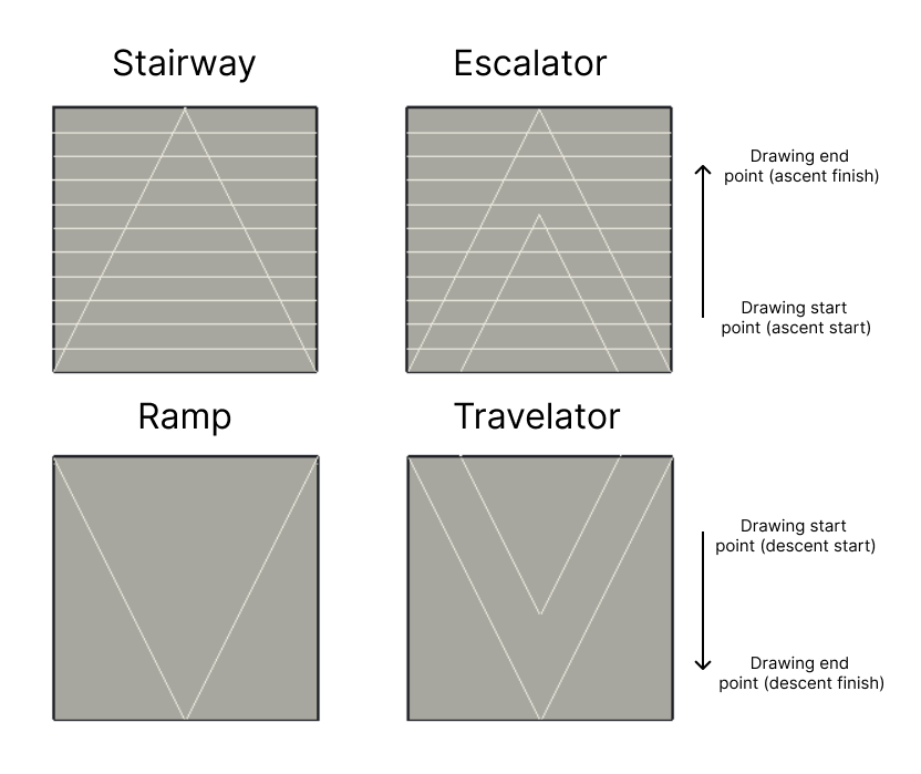
In the editor, flight types are differentiated visually by a set of drawn lines:
- Stairway and Escalator flights are marked with horizontal lines that schematically represent steps. For Ramps and Travelators, the model is displayed without the lines — representing their flat surface.
- The direction with which you draw the flight element is marked by the two lines connected at their top (the caret arrows). Drawing the element ends where the caret arrow points. Stairway and Escalator flights are drawn from the bottom to the top, while Ramp and Travelator are drawn from its highest point to the lowest.
- For Stairways and Ramps, the direction arrow is displayed with a single line. For moving flight types, Escalators and Travelator, it is displayed with two lines.
 {width=80%}
Escalators and Travelator
Two different factors influence the speed at which people move on escalators or moving walkways: the movement of the escalator/travelator belt and the movement of the people on it.
To set the movement parameters for an escalator/travelator, change the following properties in the Motion Parameters subsection of the Stairway tool:
-
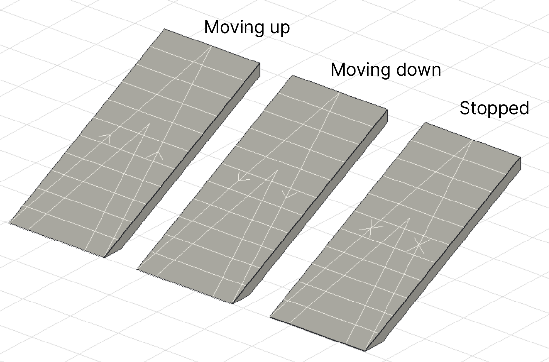
State — the operating mode of the escalator or the travelator. Available options: Moving up, Moving down, Stopped. Schematically, the state of moving up is shown by two small arrows pointing from the lowest point of the flight to the highest, while the state of moving down is shown from the highest to the lowest. The “Stopped” state is shown by two small crosses on the side of the arrow.
 {width=80%}
 -
Speed of movement — the speed of the escalator or the travelator belt.
-
People Speed Modifier — a constant reflecting the difference in the speed at which people move on the escalator or moving walkway compared to a regular staircase or ramp. By default, the value is
0.8, representing the nature of people moving a bit slowly on the moving stairway compared to the stable structures.
By default, people will not travel while crossing the moving escalator/travelator — they will stand still while it’s running. To ensure that a group of people always traverses the escalators/travelators, check the Walk on moving Escalators and Travelators option for the chosen profile in the References | People profiles editor.
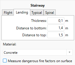
Landing
To prepare for creating a landing, switch to the Landing tab and specify desired parameters.
To draw a stairway landing:
- Mark the starting drawing point by clicking the left mouse button in the topology editor (mark 1).
- Mark the length to the second corner by clicking the left mouse button the second time (mark 2).
- Mark the length to the third corner by clicking the left mouse button the third time (mark 3).
- Specify more corners, if necessary
- Click the right mouse button to finish drawing.
 {width=60%}
Typical stairway
A common two-flight stairway consists of two flights and one landing element. The upper level of the landing will be automatically dislocated exactly in the middle of the floor.
To prepare for drawing, click
- Click the Typical tab.
- Specify the width, length or other parameters before drawing, if necessary.
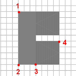
To draw a typical stairway:
- Mark the beginning of the gap between flights by clicking a left mouse button in the topology editor (mark 1, pictured below).
- Mark the end of the gap between flights (mark 2).
- Mark the spot to determine the width of a stair landing (mark 3).
- Mark the spot to determine the width and length of the flights in the projection. (mark 4)
Use Space during drawing to change the direction of ascent for the stairs. The direction of ascent is indicated by arrows on the flights. For a stair flight, the direction of the arrow shows the direction of ascent, and for a ramp, it indicates the direction of descent.
Spiral stairway
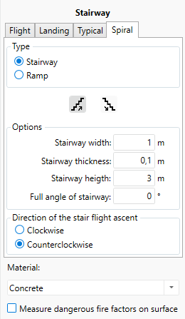
To create a spiral stairway, switch to the Spiral tab and specify desired parameters.
To draw a spiral stairway:
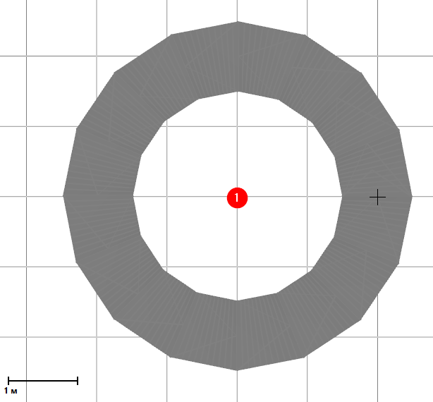
-
Define the center of the stairway with the first click of the left mouse button. After the center is selected, a single round of spiral stairway is displayed (360°), drawn in accordance with specified parameters and the radius equal to the distance from the center of the stairway to the current position of the pointer.
 {width=70%}
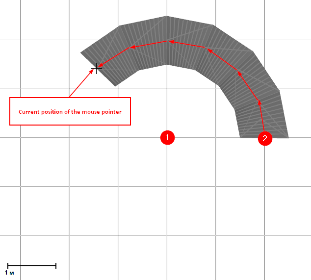
 -
Define the stair of the spiral stairway by clicking the left mouse button the second time. After that, you need to select the angle of the spiral stairway.
 {width=70%}
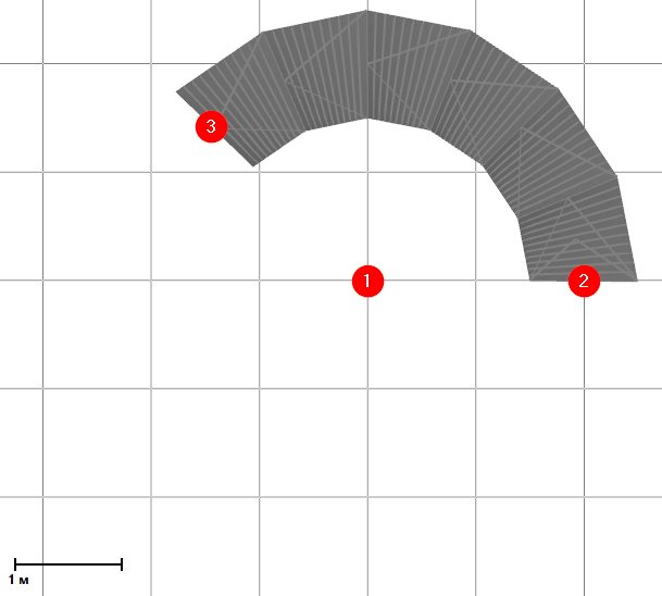
 -
Define the end of the spiral stairway and complete the drawing by clicking the left mouse button for the third time.
 {width=70%}